February 2020
Late last year I had made a decision to step up the progress on this build. To reduce some time I opted to buy engine run components as a tried and tested solution rather than putting them together myself.
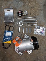
Autobionics were enlisted to provide much of this including LS3 Ancillary Drive Kit, LS3 Run Kit (ECU, modified Loom etc.), Low profile Sump kit, LS3 Oil Cooler kit, LS3 Cool Air Intake Kit and modified engine mounting plates.
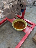
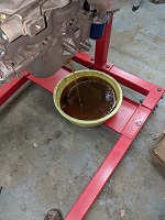
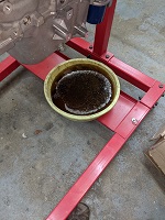
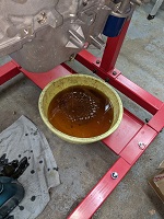
The sump that comes with the crate LS3 is quite large and protrudes below the chassis significantly - I believe it is the Camaro sump - it has the part number label 12640748 on the bottom. The replacement I have is I believe the lowest profile GM sump available, with part number 12624617. The sump kit also comes with a replacement oil pickup assembly, dipstick assembly and windage tray. Before I drop the sump off I check the drain plug for any oil, good job as it was full, I had to stop part way through to empty my catch bowl. Nearly 7 litres of oil drained out.
With the oil out it is easy enough to change the sump, oil pickup, windage tray and dipstick.
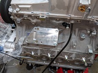
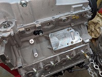
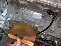
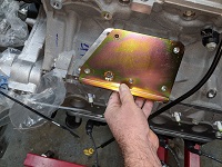
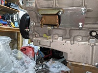
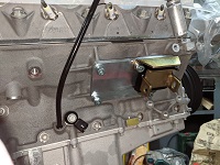
I then fit the engine mounts. The Autobionics cool air intake requires some additional space in front of the engine, to make room for this install the engine needs to be moved back 15 mm in the chassis. This is achieved using some billet engine mounting plates with the engine mount location modified.
In these photos you can see the comparison of the Autobionics mounts versus the original factory ones, the 15 mm offset for the actual engine mount to bolt on to can be clearly seen.
Both mounts now assembled to the engine, onto next job.
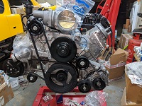
Next up is to fit the ancillary devices.
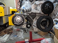
First up was the air conditioning compressor.
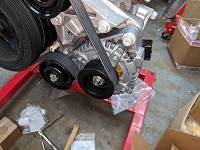
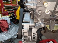
Finally the alternator and additional idler pulley were installed.
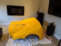
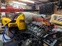
With the engine ready it is time for a first fit in the chassis and familiarise myself with space restrictions, plumbing etc. With the rear clip removed and no space in the shed I originally had built to store the body I present my challenge to the wife (reminding her that the reason the shed was 20 feet long was to easily store the body components). I assure her it will not be for very long so a home was found - she even helped me carry it in.
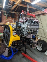
With the engine transferred to the hoist we are presented with a challenge, the engine hoist legs foul the dolly that the chassis is sitting on
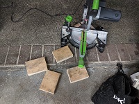
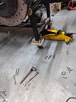
Initial thoughts involved cutting and re-welding the dolly (there must be an easier way), making blocks to go under the dolly wheels (worries about the dolly moving and slipping of one block). The solution chosen was to remove the wheels and insert a block of wood between the dolly and the wheels.
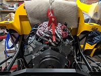
Once the dolly was raised lifting the engine into place was pretty straight forward. The pads on the chassis that the engine mounts sit had to be ground back a bit to allow the mounts to seat down enough allowing the bolts to be inserted.
The G50 gearbox adapater, flywheel and gearbox input shaft spigot bearing were also now installed. I will install the clutch later when I have made an aligning tool.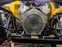
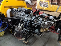
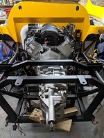
The G50/52 Gearbox was now lifted in and bolted on. The tail of the gearbox was temporarily supported with some wood. One of the next jobs will be to fabricate a rear gearbox support. The cool air intake was also installed. The cool air intake relocates the throttle body at 90 degrees to the intake manifold by a 3D printed elbow and then a second 3D printed elbow pipe is connected via silicon pipe to present the air filter at the lower front of the engine bay.
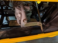
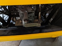
The last section of the gear shift linkage needs to be fitted.
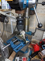
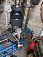
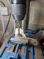
First up is to drill the end lever plate to accept the securing bolt. Centre drill, followed by pilot drill and then the final size drill.
A quick check that it fits fine.
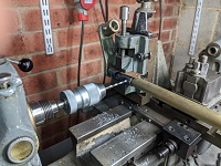
Next up is to drill the last universal joint. The same process was used as the previous joints were drilled.
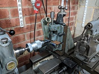
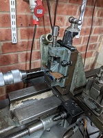
Clamp it on the lathe, centre drill and then sizing drill.
The joint is pinned to the shaft and lever plate, the shaft was then screwed on to the linkage installed in the car and the lever plate fitted on the gearbox.
After some experimentation the screwed length of the shaft was set and the lock nut tightened. All gears can be selected, but I do find it quite hard to distinguish between 1st and reverse. I'm sure that won't be so bad when the engine is running, but then again a lot of owners I believe never use 1st gear any way.

