May 2019
I want to install central locking, I look at other builds and get some ideas on how to mount the motors.
I take some photos and rough measurements of the lock installed inside the door and mock up a couple of brackets in Fusion 360.
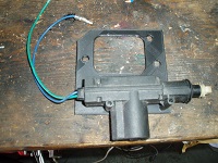
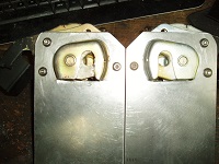
Once printed out I can perform a trial fit, the angled bracket seems the easiest way to go.
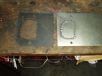
To improve the irregular shaped cut out for the lock I fill in part of the hole with a cheap 3d printer pen.
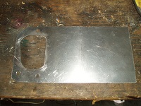
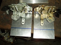
I then use this as a templte to mark out some sheet steel.
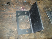
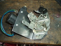
I chain drill and then file the lock aperture in the steel and drill the three mounting holes.
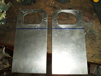
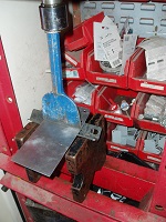
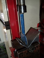
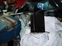
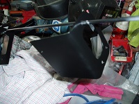
Next I need to bend the sheet to produce the right angled bracket. I mark out a line for the bend and with the use of a piece of angle iron and a bolster use the press to form the bends.
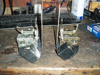
The bracket now needs the excess sheet to be removed
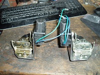
To couple the motor to the locking mechanism I use the steel rod that is supplied with the motor. A right angle is easily formed using the vice and a soft faced hammer.
Since the actuating arm will move in an arc, there needs to be some movement where the motor couples to the locking arm.
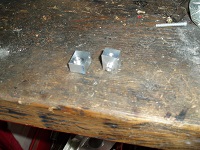
I machine some bushes out of aluminium with a shoulder to mount on the arm. The centre of this should is tapped to take a securing screw. A second hole is drilled for the motor rod to be inserted along with a threaded hole to lock the rod in place.
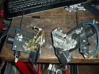
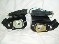
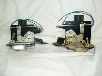
Once the locking motion has been verified to work the rods are shortened and the brackets painted.
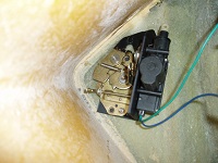
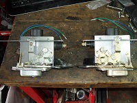
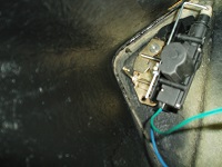
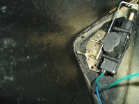
Below is the drivers door lock installed showing the Locked and unlocked position and clearances. I will need to remove it and apply some more black stone chip paint on the areas missed around that area and to complete the wiring.

